|
|
| Разместил (Author): |
SergUA6  |
| Авторские права |
© http://www.radioscanner.ru |
|
|
Текст
|
How-to : Analysis of OFDM signals in SA. The first part.
In the description of update 6.1.0.0/1 we have mentioned bases of analysis of OFDM signals. Basically, all was reduced to a search of "the magic triangle" substantiation. Below we will consider what is it purely possible to receive from this triangle, how really magical this triangle is, and at the same time we will understand how to analyze the real OFDM signals. It is supposed, that You have read the previous description, because terminology and the main idea of the previous description are necessary for this tutorial.
As it was already told, current implementation of OFDM module in SA, solves only tasks of search of LS and LG. These values are key moment in OFDM analysis, definition of these parameters makes approximately 80-90 percent of solution of analysis problem. Without definition of these values there is nothing to do and OFDM analysis becomes impossible. That's why it is desirable to know precisely range of reliability of results, which are produced by SA OFDM module, and to squeeze out of these results maximum of the possible.
The most reliable, and probably the only one correct way, it is to study behavior of SA OFDM module on the signals, which have absolutely precisely known parameters. I underline, parameters should be not known as abstract, for example "CIS-12 Tone has a rating 200 Hertz and speed in the channel 120 Hertz" - it is an abstraction, it is only the announcement of parameters, while it is necessary to have the signal, where there are those parameters, which are declared, are present with guarantee. Specially this purpose there is OCG - generator of OFDM signals, it has been written long time ago, and it is indented for tasks of search of possibilities of OFDM analysis. Let's synthesize any test signal by OCG, for example with such parameters:
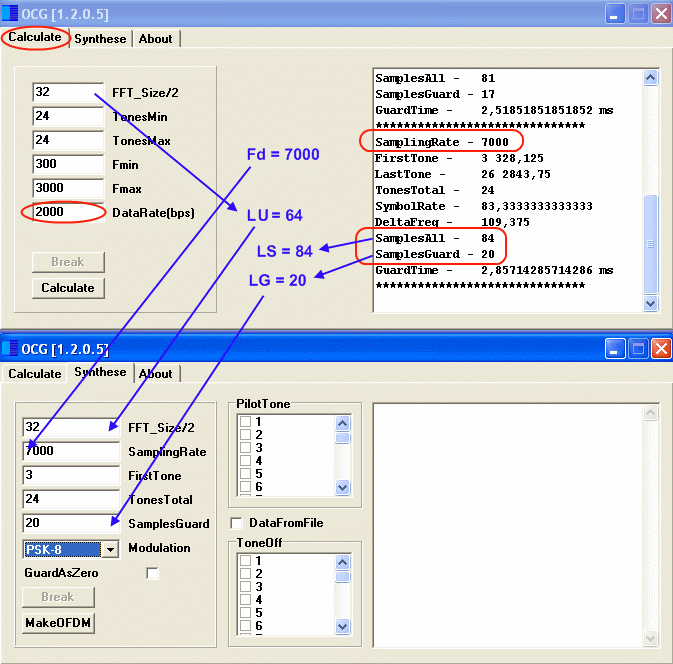
We are interested in LS and LG search most of all. LU in the given example is equal 32 (block IFFT of creation of the signal) *2 = 64, LG = 20 from settings, therefore LS = 64+20 = 84 countings for sampling rate exactly 7000 Hertz. Manipulation in the channels has rather indirect relation to search LS and LG, it simply should be, and it value does not play a special role.
Let's look, what SA OFDM module speaks about this signal, all customizations of the module are specified by default:
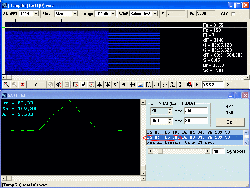
Everything is precisely as well as it should be. In our case, the signal is ideal, thus it is possible to estimate, in general, what is occurring at changing of those or other customizations of the analyzer, in particular, it is possible to estimate dependence of "the magic triangle" type from quantity of the summarized at the analysis symbols. We also can look what is occur at moving on the signal fragments in different modes. Let's do it.
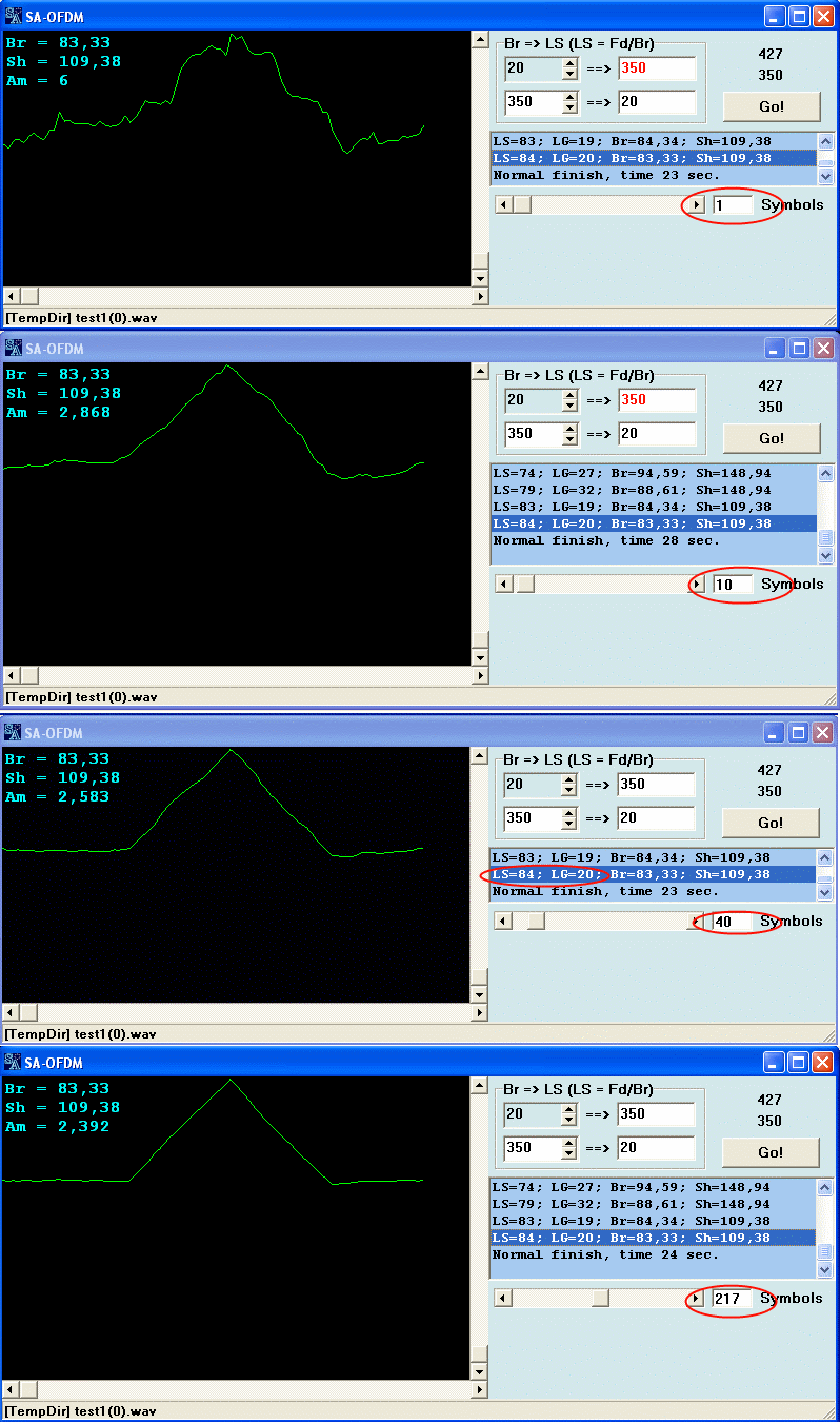
Appearance of the correlative triangle depends from quantity of the symbols participating in its creation. According to the theory the more symbols the more ideal and magical triangle we get. Move the slider Symbols and be convinced in it. It is absolutely clear, that hundreds of symbols give the very fine picture, while tens, and especially units of symbols, give the worst picture. When we will move the slider, please pay attention to the one thin moment: the top of triangle will not move from it's place! The triangle will be worse or better to look, but it will not move a little even on pixel! And it will always stays triangular by it's form shape. It is the extremely important thing.
Now it is possible to look, what is occurring at moving by a fragment of the loaded file. If to move slider on countings, by clicking on sliders arrows the triangle in the mapping window will move, it is clear. If to move symbol-by-symbol, by clicking between the slider and arrows, then, the next important point, the triangle as will not move even on one little pixel again!!!
Let's discuss the static behavior of "the magic triangle". So hard and "iron" tendency of the triangle to always stay on one place, both at symbol-by-symbol moving, and at change of quantity of the symbols in its creation, speaks about the fact that: both LS and LG are correct and absolutely precisely correspond to those values, which are found by SA OFDM module, and also it speaks, that LS and LG are corresponded to current sampling rate in accuracy.
In other words, when we are adding to triangle's creation new symbols (increasing their quantity), then we adding them with mathematical accuracy because, all symbols have absolutely exact size LS = 84 countings, and it is absolutely exactly, the first of 20 these countings of all LS are absolutely precise LG.
It should not be approximately 20 countings, but namely are equal 20 countings, which in turn, are absolutely precisely laying down on sampling rate of the file, which is precisely equal 7000 Hertz. Same thing is occurring at moving on the file symbol-by-symbol, we are absolutely precisely moving in steps by LS countings.
This is an ideal picture, on the ideal signal, and that is how it should be in the theory, and in practice, on an ideal signal. But You will never see such picture in reality:) In reality, you will observe some close picture, and closeness to the ideal will tell about that, how much parameters, which you have received far from real, and how strongly it is possible to trust them.
Thus, now we can consider real signals/records and following problems.
The first question, Does the magic triangle has always positive peak? And, in case, if no, then why and which triangle should be considered as the correct one? A good question. Besides, if you will try to synthesise a signal in OCG with the negative correlative triangle, you will not be able to do it. Why?
I will not go deep into details, but let's consider this question.
the negative peak on the correlative triangle says that the current fragment LG corresponds to end of LS with "the other way", in other words in an antiphase by amplitude.
It means, that LG in such symbol it is not simply copy of LS end, and inverted by an amplitude copy. Standard FFT/IFFT algorithms, which are usually used at OFDM creation, are not able to cuase such effects(althtought it is possible to do it artificially, but there is no sense in it). But it's quite another if it turns out automatically, as a result of some special creation, what is that special creation?
The usual grid of frequencies of standard FFT/IFFT algorithms represents even and odd harmonics of the main step. For example, we have step in the grid in 100 Hertz, therefore we will have the grid from the frequencies=K*100, where K can get values from 0 and to any value, that is the grid of frequencies looks like this 0-100-200-300-400-500...and etc.
You will not be able to generate the grid in the centers/positions of the current grid. For example, such grid 50-150-250-350-450. This grid is distinguishes from the previous by shift on dF/2 value at the same step in 100 Hertz, this grid is also consists not of the sum of all harmonics of the main step, but of the sum of odd harmonics of a half step. On such grid the similar signals are formed.
From all this, it is important to understand that there are signals, which are created in the standard grid and in not absolutely in the standard.
The first type of signals has positive correlative triangle, the second one the negative. Here follows the question: if we will shift a standard signal upwards on the half-step or downwards, will gain the same effect of the negative triangle? Certainly we will!
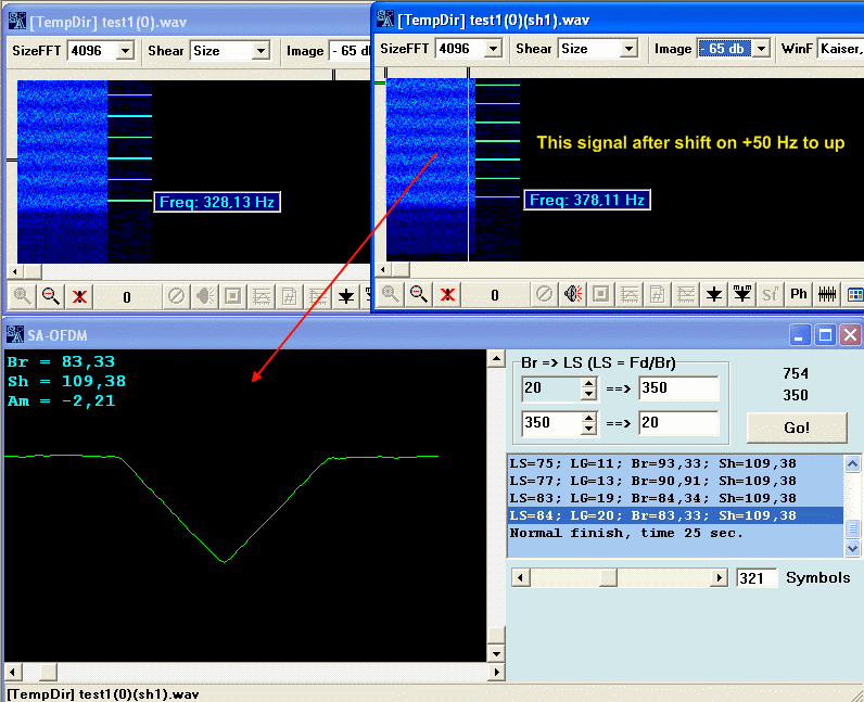
Thus, there is dilemma before us. If we analyze unknown by default OFDM signal, where is the guarantee, that it has no shift and how to get to know then, which grid was initial for this signal, the standard grid or grid on odd harmonics of half step?
And there is no problem!
From any signal, it is possible to receive any kind of a triangle what is pleasant, positive or negative by simple shift on frequency, as any signal can be transformed into both in standard, and in the one which is created on odd harmonics.
It is much more important that the signal's shift by frequency, leads to change in appearance/shape of the "magic triangle", and on this sort it is possible to judge, has the signal has got the standard grid or it has overstepped the bounds.
The signal's shift by frequency on exactly one step, does not change neither polarity of the triangle, nor its sort. It means that concrete signal OFDM is always located on the one place, if it precisely gets into grid positions. We can select any grid, which is pleasant to us, even if the position of channels on this grid differs from the initial, the signal still stay on the same place, because positions on an orthogonal grid of frequencies, are equal in rights and have no special own individualities.
But what will be if the signal does not get into any of grids precisely? Nothing really bad, in this case, there will be two "magic triangles", one with bigger amplitude, another one with smaller. SA will output both triangles or one, depends on their appearance/shape. Usually, the triangle with bigger amplitude is shifted to that grid closer.
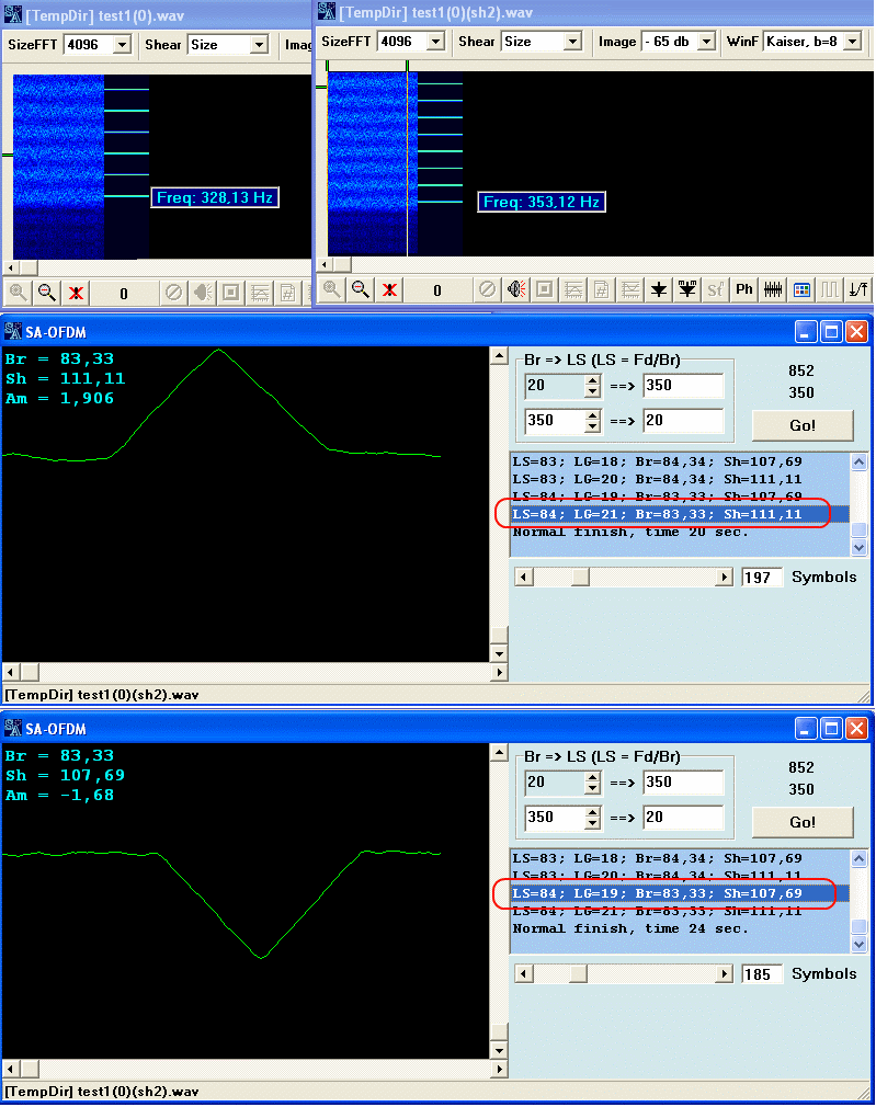
As it is visible, the signal's shift in "bad" positions by frequency, changes and breaks the picture of exact location LS and LG. The values has already changed to anthers, they are not corresponded with real values, and there are already several values, but still here we see the important feature: the triangle still saves it's "obstinate character" and it will stand on it's place both at symbol-by-symbol moving on the file, and at change of quantity of symbols for correlation calculation, besides the triangle is still saving attractive enough view of a correct triangle, at all these actions.
Let's sum up this infromation: the signal's shift by frequency, leads to:
- change of a maximum level of amplitude of a correlative triangle,
- to polarity change,
- to disturbance of exact definition of LS values and LG
If instead of one maximum, we have several maximums with different polarities, naturally they will have different positions, but shift does not break the common form/shape and behavior of the triangle, because file or signal discritization is responsible for it.. Let's consider it.
Let's change file’s sampling rate, we will make it 7022 Hertz for example, and we will repeat all from start.
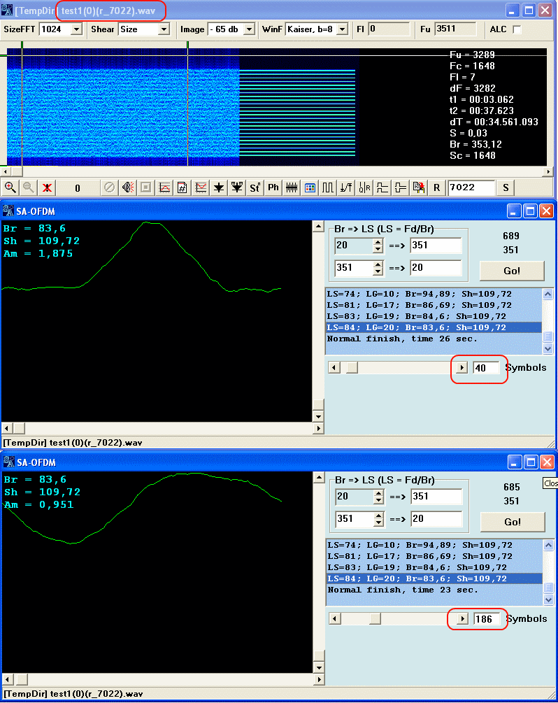
Despite the fact, that formally LS and LG have the same values as earlier, speed and spacing(rating) has been changed.
Besides, the correlative triangle now is not such "obstinate" as before, and its shape becomes worse even at increasing of quantity of the symbols for calculation.
At symbol-by-symbol moving, the traingle starts to "overlap" and change it's shape form to unrecognizability and even change polarity. This is direct result of the fact, that now there are no 20 countings LG in 84 countings LS, and LS itself is not exactly equal to 84.
And when we increase quantity of symbols for correlation calculation, instead of accumulation of results, there is their dispersion, because all exact mathematical relations, which are characteristic for OFDM signals on their native frequency of discritization, are broken.
That's why we do not recommend to take at once for the analysis many symbols: 30-40-50 is more than enough for previous definition of parameters.
In practice, you have the complete complex of problems at once: not native sampling rate, shift by frequency, and in completion to all - the signal drift by frequency in time.
If at such input data to change analysis initial conditions, for example to take at first 20 characters, to receive any values LS and LG, and then to take for example 80 characters and in additives to shift an initial analysis point, chances to receive different and occasionally very different results are very great.
That's why in current implementation of OFDM module, it is necessary to speak about exact values of parameters carefully.
From all written above you know:
what "the magic triangle" should look like for the signal , which is located on right place by frequency, and has correct digitization of the file.
The task was to show what is possible to learn/understand/define with the help of current implementation of SA OFDM module and small "magic triangle":).
Good luck.
|
|
|
|
Добавлять комментарии могут только зарегистрированные, активировавшие регистрацию и не ограниченные в доступе участники сайта!
|
| Файл создан: 21 Oct 2009 21:56, посл. исправление: 22 Oct 2009 23:29 |
|

