|
|
| Разместил (Author): |
SergUA6  |
| Авторские права |
© http://www.radioscanner.ru |
|
|
Текст
|
SA - Phase plane. Angles measuring..
First of all it is necessary to check Angles mode in SA, for this purpose, we can take a known signal (bad idea) or to synthesize in OCG one channel with the necessary manipulation. I prefer synthesized signals as everything is guaranteed, besides, for control tests ideal signals are required.
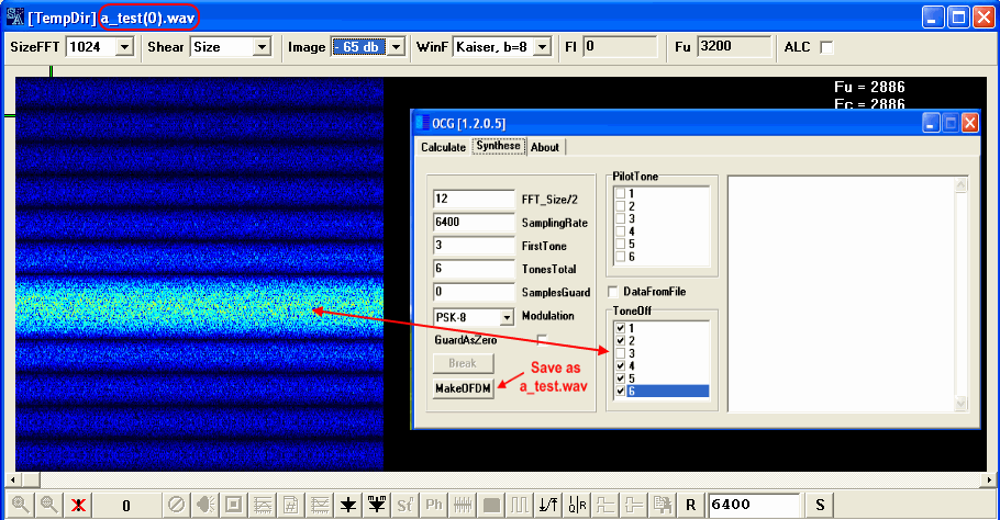
The clock frequency and frequency carrier, in the synthesized signal, are not important for now. Let’s synthesize, for example, PSK-8 and check up what shows SA in the mode of Angles measuring.
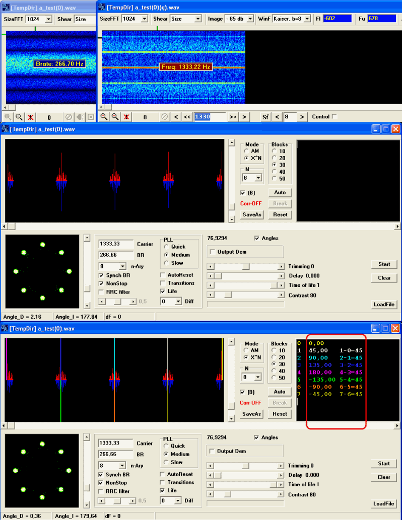
Everything looks convincing and correct enough, but there is one nuance, which should be considered.
PLL in SA provides Synchronization by frequency carrier, actually, this synchronization actively enough compensates attempts of deviations of carrier oscillation, it is the task of each PLL system, and it can distort a true picture of angles allocation in a signal.
PLL in SA has three modes:
Slow- it is very soft mode, it does not influence obviously on allocation of angles in constellation. It is better to use this mode for exact measurements, when it is desirable to eliminate any possible reasons of distortions brought by SA.
Medium - this is also soft enough mode of deduction of synchronization, but PLL operations are much more active and more effective, compulsory deduction of angles is possible in necessary situations.
Quick - this is an aggressive PPL operating mode, in this mode PPL is "stalking" the signal in the slightest attempts to deviate expected value literally. For angles measurement this mode do not suit, as the real picture in the signal will be displayed not correct, because this picture will be represented as PLL "wishes" to see it. In this mode, if n-Ary does not correspond to real modulation in a signal, chances to get "not clear picture" are rather great, as PLL starts to "hold" everything. But if the mode corresponds, then, in case of the big mistunings, it allows to bring SA on working positions of clock and carrier frequencies in the signal very fast and effectively, after that it is possible to switch on Medium mode. For example I often use it, if the signal allows it and there is such necessity.
It is possible completely to disable PLL response on carrier, having installed mode n-Ary equal 1. In this case, PLL does not make any attempts to watch for signal's carrier, but attempts to hold the clock frequency are always undertaken (another PPL works), and to minimize this influence is possible only by having working in mode Slow, it is impossible to switch it off.
Actually all modes are necessary, all of them are used in solution of practical tasks, and the choice of this or that mode depends of what You are interested in at the current moment.
Standardly measurement of the angles is better to realize in Medium or Slow mode, results are exact enough.
In special cases, Quick mode and full switching off of synchronization by carrier, through n-Ary = 1 are used.
You can spend measurements in the signal a_test.wav in mode Slow, and you will be convinced that the result will be similar to the previous.
Thus, we consider, that an introductory part and pre-check of the new tool is completed. All works correctly, results are reliable, nuances of operation of the module are known. It is best time to start real measurements, on the real signals.
I suggest to consider one of channels of signal DIGTRX , which has brought us many problems, in the past, with reception of exact parameters of modulation.
Let's take the fourth channel from below. The signal is rather qualitative, and the seventeenth harmonic gives a classical picture that assumes usage PSK-17, as the ninth harmonic gives something similar to PSK-9, but strongly blurred, probably 9 is not exact value, but close to it.
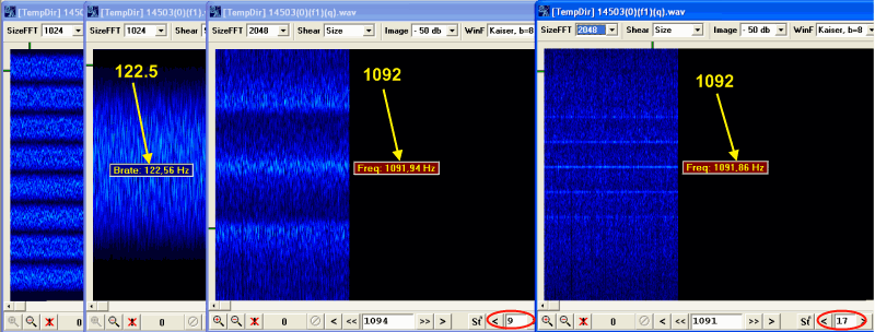
Nevertheless, both in mode Medium and Slow, PSK-17 is obviously enough displayed on Phase plane, and in a relative mode we can see picture PSK-9 with strange enough allocation of points.
For finding-out of the details we will take an advantage of new possibility to measure angles in constellation, and we will try to understand what modulation in DIGTRX actually is.
We will try to eliminate influence SA on result as the objective picture is necessary to us.
Let's start Phase Plane operation with n-Ary = 17 and mode Medium, after reaching of steady synchronization, we will go in mode Slow, the picture will be steady in this mode, we will eliminate operation PLL as the possible interfering factor having installed n-Ary = 1, and we will switch on mapping of the first difference(as in an absolute mode the chaos in connection with absence of synchronization by carrier will start).
Let's activate mode Angles, and after we get enough of the data, we will spend measurements which show very interesting and tangled picture.
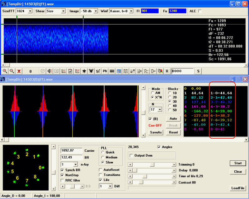
It is well visible that though angles are symmetric concerning a zero vector, their values accept rather exotic values, from maximum approximately in 45 degrees, to minimum in 28. No any multiplicity is observed between corners, neither in 360/17, nor in 360/8.5
There is a sense to look that turns out on the Phase Plane in a mode n-Ary = 9. As mode Medium does not cope with synchronization tasks on carrier, we use Quick mode. At the same time also we will spend measurement of angles, although we do not expect any surprises here, PLL will maintain in every way "correct" angles.
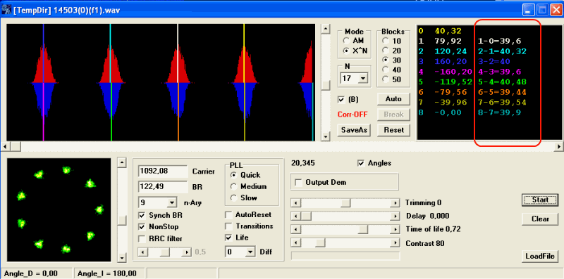
Predictably, angles are "correct" approximately 360/9 = 40. But points remind small triangles, and it explains all!:)
There is a method of lowering of the peak-factor of a signal named "nonlinear compression", it is widely enough used at QPSK modulations, ( as we can see not only). In a general view, sense of the method, that strictly dosed out controllable distortions are brought in a formed signal, in the form of the set admissible dispersion of amplitudes and phases, it allows to reduce considerably sometimes peak-factor, without essential deterioration of a noise stability. Thus, as a rule, compatibility with existing demodulators is provided.
Positions of points of constellation at such compression, occupy the permissible limited sector ,which sizes depend on compression parameters, that complicates the analysis of similar signals, and sometimes leads to false conclusions, for example, as in this case, it can seem that differential PSK-17 is used , while it is absolute PSK-9(or specail DPSK-9), and to the signal one of methods of lowering of the peak-factor is applied.
Other interesting signal, which we will consider, is DCF77. German standard of time and frequency. , it is easily finds out and the clock frequency is approximately equal 646 Hertz, it is already the very good sign, as without reception of clock frequency the analysis practically is not possible.
Let's define modulation mode, PSK finds out confidently, but to tell precisely without measurement of the angles, which mode is used is problematic enough. And for reception of a bit stream atleast with any minimum guarantees, it is extremely desirable.
The Problem in that only two positions of the phase are used, to define the angle between them without exact measurements is hard.
Frequency carrier 1493 Hertzs is visible on the signal, and it is well visualized on the second, the third, the fourth etc. harmonics, that is strange enough.
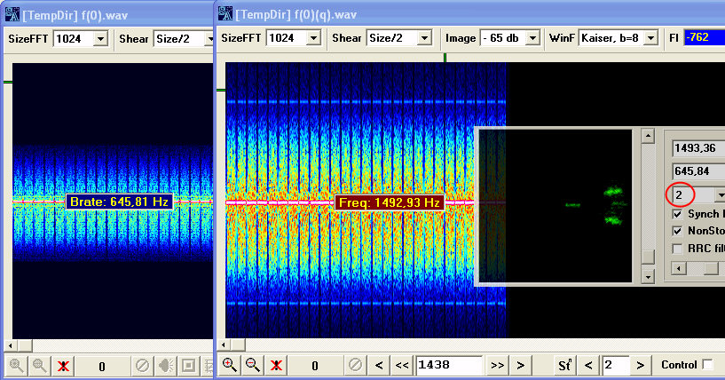
There are two points On a phase plane , the angle between them is the angle we are interested in. How to solve this task is already known. Measurements can be spent as in absolute operating mode Phase Plane, in the relative it is usually measured by two reasons:
1) if there is really relative modulation
2) or if by some reasons the constellation does not manage to be held motionlessly(such happens if the exact order is unknown or is not defined, or there is no synchronizations on the carrier).
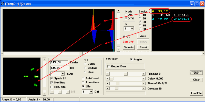
As it is visible, the angle is close to 31-32 degrees, besides, there is an obvious asymmetry, which is not noticeable on the Plane, but is perfectly visible on the histogram. At the same time in the description of signal DCF77, it is told about + / - 13 degree phase-manipulation, that is, deviation of the phase relative zero should be 26 degrees.
The error is great, it makes more than 20 %. Probably, there is an error in description of the signal, and the real manipulation is + / - 15 degrees. That is much more logical, because "good" multiplicity pi/12 turns out. In favor of this version, tell results of measurement of angles of manipulation on other record, where it is close to + / - 15.
In the present state of affairs, when we have the signal, from two different receivers, and measurements we get manipulation angles is + / - 15 degrees, our opinion is that we can trust the analysis, than the description. Although two records are not enough to proclaim surely that there is an error in description, and probably such considerable discrepancy has under itself the objective reasons.
Good luck~
|
|
|
|
Добавлять комментарии могут только зарегистрированные, активировавшие регистрацию и не ограниченные в доступе участники сайта!
|
| Файл создан: 28 Jan 2010 00:53, посл. исправление: 28 Jan 2010 01:07 |
|

