|
|
| –азместил (Author): |
SergUA6  |
| јвторские права |
© http://www.radioscanner.ru |
|
|
“екст
|
Modules involution(getting of the signalТs harmonics) and Phase Plane.
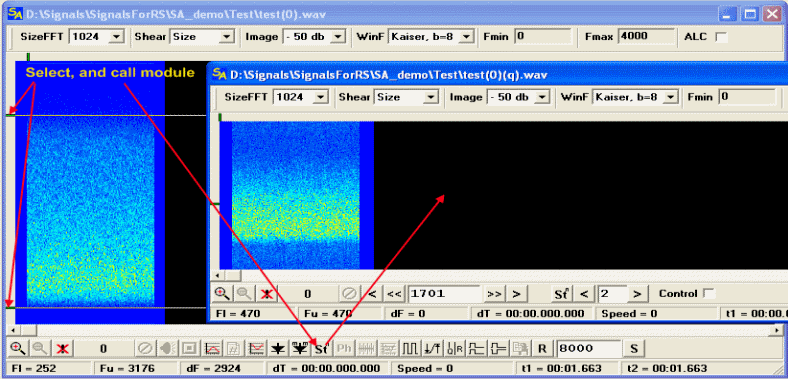
Involution(getting of a signalТs harmonics) of signal is widely used in the signals analysis allowing to define, in some cases, the arity(n-ary) of the phase-shift manipulation, and also to receive a value of the carrier frequency.
Upper toolbar and lower information fields are similar by their functions to the main working window, therefore we wonТt consider them.

1,2,4,5 ЦThese buttons allow to set a value of the frequency of carrier oscillation in a window 3, with an accuracy in one hertz.
3 Ц frequency of the carrier, relatively which involution(St^N) of the signal is occurring.
6 Ц Start of the performance of calculation with current settings. It can be called at any moment.
7,9 Ц setting of necessary studying harmonic of the signal.
8 Ц indication of the studying harmonic of the signal.
10 Ц show on of the marker line on the frequency in 3 field. Allows to get exact value of the carrier frequency, by combining lines on a spectrum with a marker. But after appearance of possibility of direct measurement of the frequency on the spectrum, it is rarely used.
Pop-Up menu of the module involution.
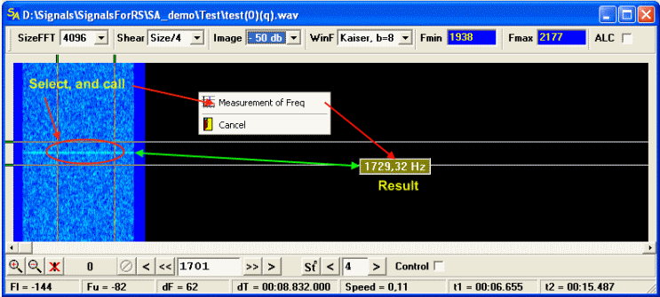
Measuerment of Freq Ц Same as in the main working window, demands selection of the segment of measurement with V and H markers, the result of measurement also comes back in the form of the floating window. Accuracy is approximately 1-2 hertz, despite it, speed of calculations lower, than frequency direct measurement in the main working window. It is important that last measurement is adding in the module of a phase viewer in the Carrier field.
Work of the program inside the module of power is much slower then just studying of the spectrum in the main working window. ItТs because calculations which are necessary for getting harmonics are hard enough and it is required much more time on the spectrumТs construction.
Module PhasePlane(phase viewer).
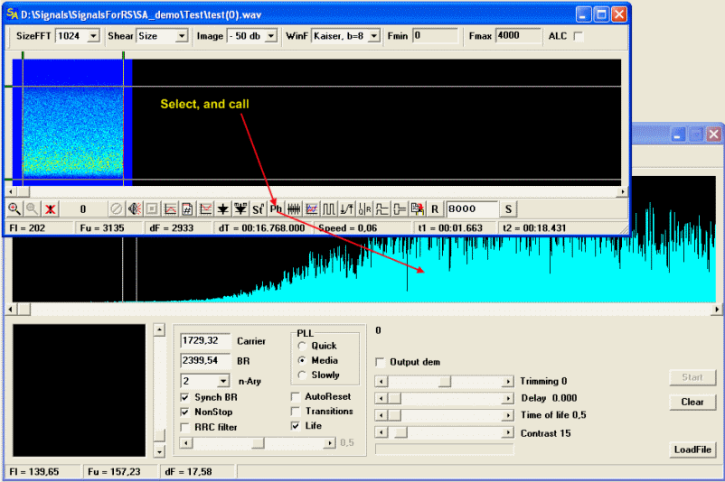
Tools of the PhasePlane.
Several words about PhasePlane module, this module solves two tasks :
1) display of the graphical spectrum with high-resolution
2) tasks of different signals studying on phase plane
The window of this module canТt be scaled, it has fixed size. By default this module is called for spectrum review, switching in mode Phase plane occurs at file loading, through the button LoadFile.
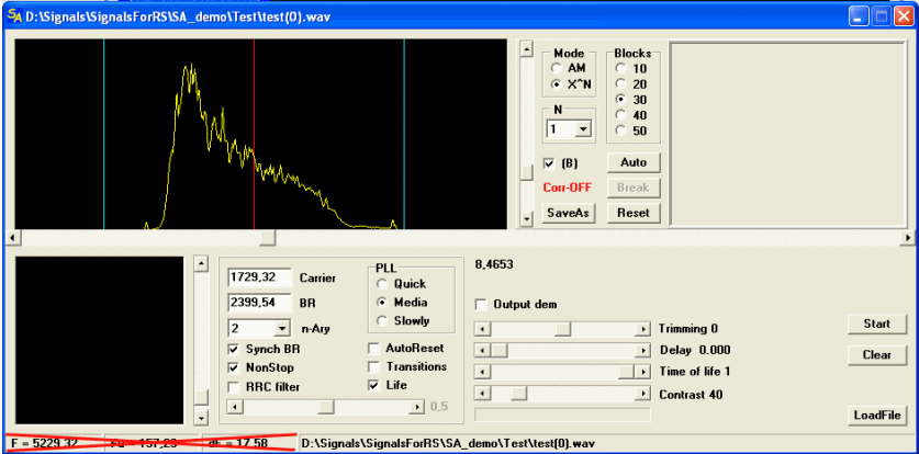
Using of PhasePlane for review of the graphical spectrum. Lower area do not have relation to this task, itТs crossed out with red lines.
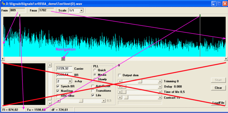
Upper toolbar and indication windows
Fmin Ц frequency of the left verge of displayed graphic.
Fmax Ц frequency of the right verge of displayed graphic.
Scale Ц scales graphic in the displaying window
Navigation Ц moving of the graphic, if itТs possible
Lower bar of indication windows.
Fl Ц frequency of the left marker
Fu Ц frequency of the right marker
dF Ц delta of the frequencies between makers
Using of the PhasePlane for studing of different phase signals.
Loading of file
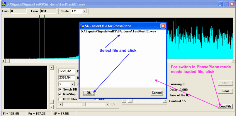
Phase Plane mode
Instruments and elements of an indication
The Form is separated on two parts: upper and lower. Upper part, including SchrollBar, concerns to the semi-automatic ISD (InterSymbolDistortions) corrector. Lower part is the phase viewer itself. Both parts are tightly connected and represent the very powerful instrument.
ISD corrector Ц elements of indication and control.
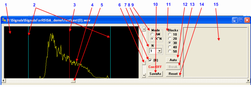
1 Window of graphical displaying of the signal
2 Lines of the prospective sides for X^N mode, or one line of the clock frequency for AM mode.
3 Line of the prospective bearing frequency. It is frequency of PPLТs work.
4 The Signal itself, represented in that mode, in which ISD corrector works.
5 Navigation on the loaded file, where left extreme position Ц the file beginning, right Ц the end.
6 Regulation of the graphicТs scale by vertical axis
7 Mode of correctorТs work, B(check-on) improved algorithm of the calculation, B(check-off) another one. In Mode = AM doesnТt mather.
8 Harmonic of the signal, with which corrector does work.
9 Mode where corrector is situated. In other words mode by the clock frequency, or mode with harmonic of the signal by carrier and sides
10 Saving of the processed signal in the file.
11 Number of blocks in the sampling of the signal, with which corrector works. More blocks more accurate corrector does work(and slower).
12 Calculation of the signalТs block by the corrector. A single step.
13 Stop the calculation of the current step, in case if the calculation is unreasonably long.
14 Reset of the corrector to itТs initial zero state, that is actually correctorТs turn off.
15 Window of output of results of PSK signals demodulation
Phase plane
Elements of an indication and control

1 Window, where phase constellation is constructing
2 Regulation of the image scale
3 Regulation of the alpha parameter of the RRC filter, if itТs turned On.
4 On/off of the RRC filter
5 On/off of the continuous work.
6 On/off of the clock synchronization
7 The arity of the signal modulation, allows to set any arity in 2-32 band.
8 The clock frequency of the signal
9 The carrier frequency of the signal
10 On/off the dynamical show of the constellation
11 Mode of constellationТs displaying: points(dots), conversions, trajectory of the points(dots) move.
12 In the case of active NonStop, resets internal generators and PLL loops into initial stateS on the end of the file. It is necessary, if the signal has constant float by the frequency, for example: the records of satellites or etc with very big Doppler effect.
13 Control of the constant of time PLL. Has 3 modes: slow, medium and fast.
14 Relative relation signal/noise. Remained from the old versions of ISD corrector. Allows to estimate relatively quality of the signal.
15 On/off of output of the demodulation bit-stream(only for PSK modes).
16 Exact tune of a phase, sometimes it is necessary and even very much.
17 Real delay, it is needed on very short signals and very fast PCs.
18 Relative delay, in general case itТs establish number of pixels that will be contained in the window of constellation at the same time, while dynamic graphic displaying is turned on.The More pixels, the worse dynamic and vice versa.
19 Brightness of the pixels in the constellation window.
20 General indicator of all processes in this module.
21 Call of the file list, which can be loaded into the PhasePlane.
22 Erasing of the displaying window. Necessary when dynamic image is tuned off.
23 Start/stop of the constellation displaying process. After stop start will begun only from the beginning of the file.
24 Name of the loaded in the module file.
next...
|
|
|
|
ƒобавл€ть комментарии могут только зарегистрированные, активировавшие регистрацию и не ограниченные в доступе участники сайта!
|
| ‘айл создан: 17 Apr 2009 22:38, посл. исправление: 27 Feb 2011 21:54 |
|

