|
|
| Разместил (Author): |
SergUA6  |
| Авторские права |
© http://www.radioscanner.ru |
|
|
Текст
|
Getting and measurement of the clock frequency.
It’s almost the most important and sometimes quite difficult task. If it is not possible to receive and measure the clock frequency, then the chances of success are melting rapidly, and vice versa. Relatively easy to get the clock frequency out of FSK, PSK, QAM signals. Quite hard to get it out of OFDM and MFSK signals. The standard tool for the clock frequency getting is the amplitude detector, but quite often it does not work. SA contains the modified amplitude detector, which was designed specially for MFSK signals. The modified amplitude detector does perfectly deal with situations where the simple amplitude detector gives up. These two tools are supplement each other and solve practically any of tasks of getting the clock frequency.
FSK-2
The example of FSK-2 CIS-40.5 , it seems like this task is for the classic amplitude detector, but it is far from it, please pay attention that the low clock frequency requires, for its visual detection, active applying of the ZOOM and other elements of the upper toolbar.
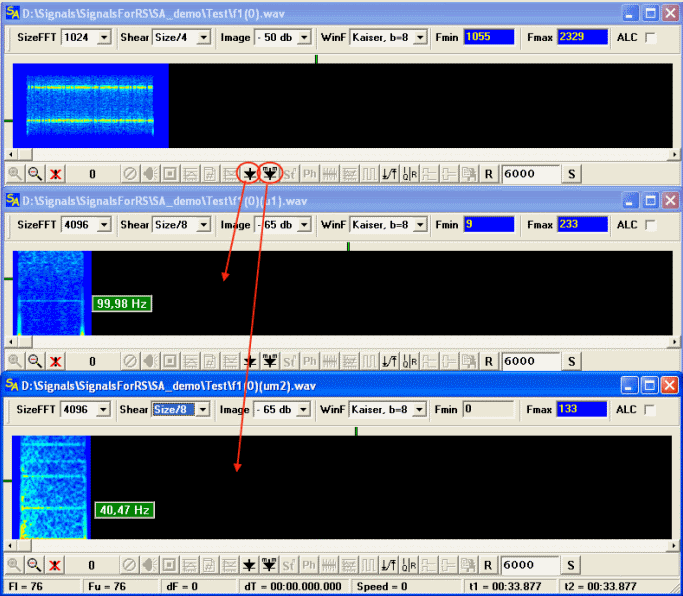
As we can see the classic amplitude detector gives ~100 Hz of the clock frequency, while the modified amplitude detector gives ~40.47-40.5Hz. There are minimum 2 reasons for it: 1) We hadn’t filter(separate) the signal from the noise before getting the clock frequency 2) The signal has multiplicative interference by the frequency in 100 hertz. The real clock frequency is ~40.5 hertz of course.
Another similar example is Greek Mil Check it up and you will see that the classical amplitude detector gives very not accurate and mixed up picture, while the modified amplitude detector gives clear, accurate and bright picture.
MFSK
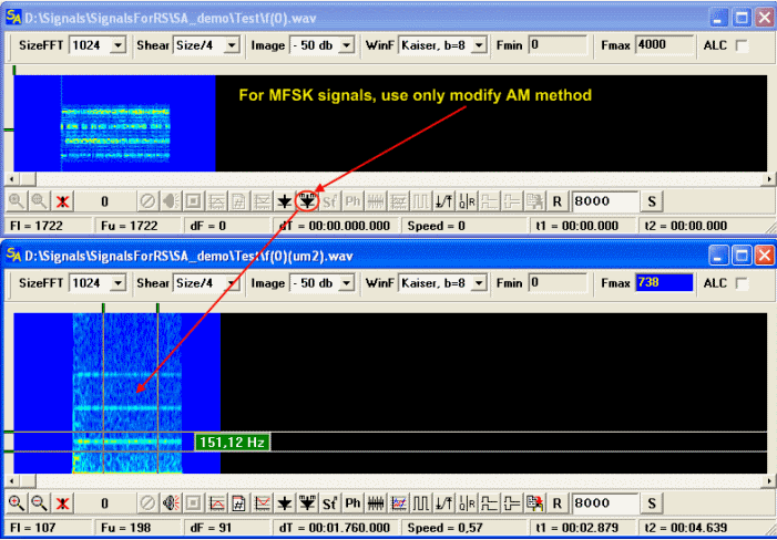
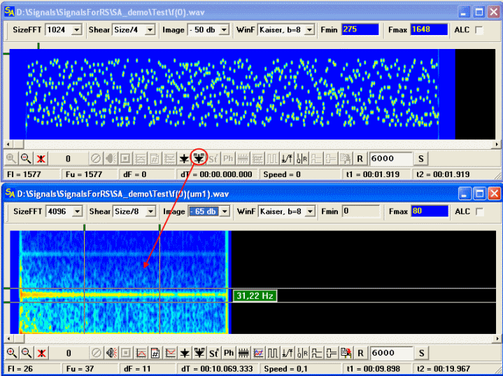
Attempts to receive the clock frequency for MFSK signals through the classical amplitude detector practically are always doomed to a failure, in this case, it is necessary to use only the modified amplitude detector, created specially for these purposes. I will not even bring examples with applying of the classical detector, because the results it gives are certainly worse and, as a rule, they are generally not even present.
The Example Alcatel 801H 4-Tone
Example Olivia
PSK and QAM
For such signals, getting of the clock frequency of manipulation isn’t that hard. The classical amplitude detector easily solves this task, with the exception of cases, when distortions in the channel so much destroy the signal, that the clock frequency is problematically detected. In some cases, the modified method helps.
The example: Italian MIL 1200 PSK Modem
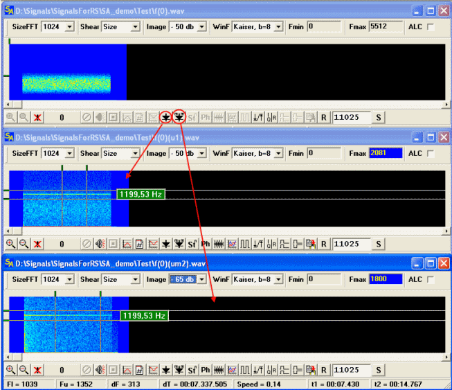
Both methods work approximately equally on the good signals, classical method does work even better, because the line for it is brighter and there are less of noises. On the bad signals, the situation can change and the modified method can give much more confident picture.
OFDM
Getting and measurement of the clock frequency for OFDM signals is extremely not simple task, and SA does not represent absolutely guaranteed methods, but SA gives some developments in this direction. Features of the formation of OFDM signals, allow to detect and measure the clock frequency in the most of cases. The small trick is used: the clock frequency of OFDM is usually represented as the out-of-band(out of range signal) harmonic noise with low intensity, the powerful signal simply beats up this noise at attempts to apply classical amplitude detecting, therefore, if you will remove the main OFDM signal from the record, then the residuary harmonic noise can be investigated for the getting of the clock frequency by the standard tools. This trick does work in 99% cases. It is necessary to consider that the level of this noise is small enough and has maximum amplitude in immediate proximity to the signal, therefore, needs to cut the signal or select the noise as precisely as possible. You can also take the noise higher or lower by the frequency of the signal, or both parts at once.
The example: Globe Wireless
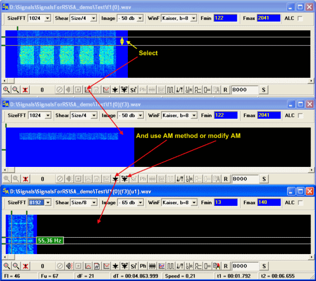
Here are the main methods of obtaining of the clock frequency manipulation from the various signals, it is, certainly, not all that is in the arsenal of the analyst, but it is the most universal and often used methods. In the description of the tools it was already said, that the frequency measurement on the spectrum through the function Measurement of Freq has an accuracy in 0.1 hertz, and the last measured value at the call of PhasePlane module is brought in the BR(BaudRate) field of this module, thereby, preparing the module for that signal, which is parsed and can be loaded in the PhasePlane module.
next...
|
|
|
|
Добавлять комментарии могут только зарегистрированные, активировавшие регистрацию и не ограниченные в доступе участники сайта!
|
| Файл создан: 18 Apr 2009 17:25, посл. исправление: 21 Apr 2009 23:44 |
|

