|
|
| Разместил (Author): |
SergUA6  |
| Авторские права |
© http://www.radioscanner.ru |
|
|
Текст
|
GMSK и OQPSK.
Some aspects of the analysis.
OQPSK and GMSK are tightly connected, as well as SDPSK and CPFSK, as well as pi/4 DQPSK and C4FM.
Such "dualism" is spread enough, and connected/linked by the fact that often some modes of frequency shift keying at some conditions, smoothly flowing and/or aspire to acquire the shape of phase manipulation.
*** GMSK ***
The general features of GMSK manipulation formation, we had already considered in the article FSK, GFSK, MSK, GMSK and some other modes.. Also it was marked, that application of the filter of the Gauss allows to narrow the main spectrum of a signal considerably.
The filter of the Gauss is characterized by parameter BT, interested ones can independently learn this subject, us interested in the practical for the analysis moments.
The value range of parameter BT lies within 1 > BT > 0 limits. The lesser BT value, the more compact spectrum at resultant signal GMSK.
GMSK with the filter of the Gauss with BT = 1, is turning into classical MSK.
For formation of GSM signals the filter of the Gauss with BT = 0.3 is standardly used, and on an example of the synthesized signals it is possible to look as it looks from positions of tasks of the analysis.
Some preliminary remarks.
As, the finished result of concerning of GMSK nuances will be some conclusions about signal TETRAPOL , then the synthesized signals have the same speed of manipulation equal 8000 Hz.
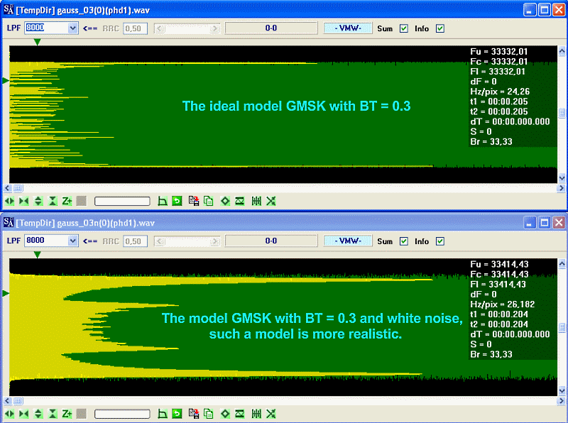
Besides, sometimes I will add a bit of white noise in the synthesized signals, because ideal signals though look beautifully, nevertheless, having absolute accuracy, in some cases these ideal signals conceal/hide the general details or make these details badly watched. This moment should be well clear from a picture below.
GMSK with Gaussian filter and BT = 1 ==> MSK.
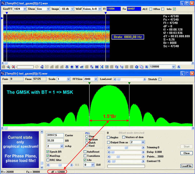
Predictably, the main energy is concentrated in a band 1.5*Br, side lobes though have relatively big level, nevertheless they can be suppressed/deleted are effectively filtered without damage to quality of demodulation. As MSK is not so interesting to us, we will only mark that level of side lobes falling slowly enough.
GMSK with Gaussian filter and BT = 0.3, the classical area of usage GSM. We will give more detailed look on this signal/model.
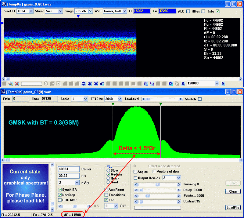
At this signal the main energy is concentrated in a band smaller than at MSK, and besides speed of attenuation of the side lobes is considerably higher, and as consequence the spectrum is much more compact. Level of the first side lobe of the order -40 дб (at MSK ~ -25 db), the second ~ -70 db. On this model, the second and the subsequent side lobes are almost indiscernible in SA.
Features of GMSK with Gaussian filter and BT = 0.3
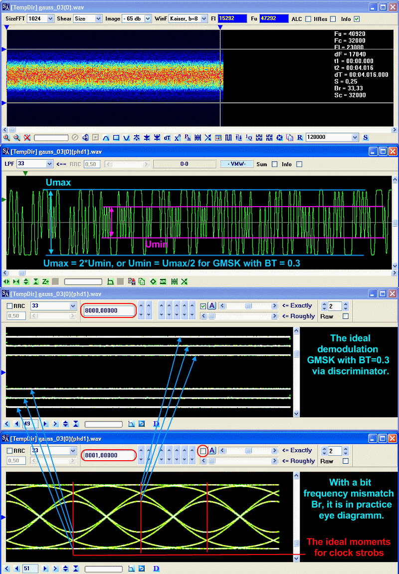
It is well visible, that after demodulation through the frequency detector/discriminator, the amplitude of transmissions/pulses having minimum duration(T) less in twice, than at transmissions with durations >= 2*T, and the general noise immunity is restricted by this. For this reason noise immunity GMSK is lesser than at MSK. In MSK all transitions/pulses are independently from duration having identical amplitude. It is “the price”, for more effective utilization/use of the spectrum than at MSK.
At the small detuning of clock rate of manipulation, in the general-purpose demodulator SA, it is possible to watch "the eye diagram", this diagram is typical for this signal.
Very interesting looks GMSK with BT = 0.3 on a phase plane in various variants of display.
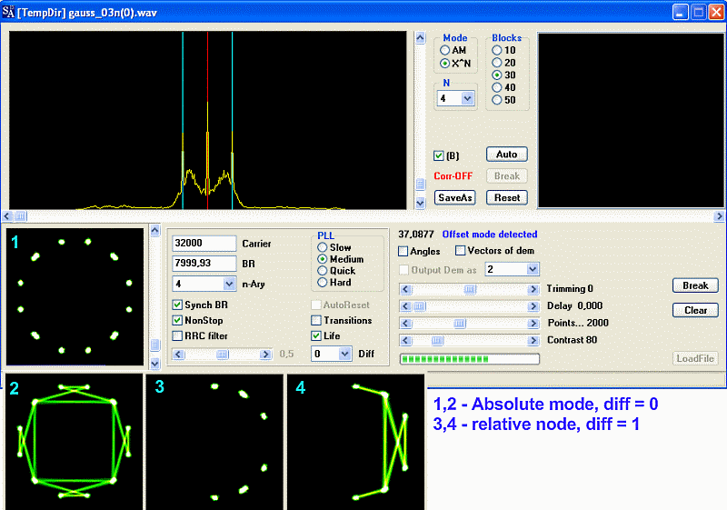
There are surely weak similarity with OQPSK.
To be honost, it seemed to me that GMSK with BT = 0.3 good enough decision, where by the cost of small impairment of noise immunity suppression of the out-of-band side lobes at rather high level is reached, and the further reduction BT is hardly expedient.
However the practice has shown that it is not so, and the example to it is signal TETRAPOL . It was a little unexpected to find out that in this signal BT is less than 0.25, and in my example it has appeared what, it is approximately equal 0.22!
GMSK with BT = 0.25, area of usage TETRAPOL .
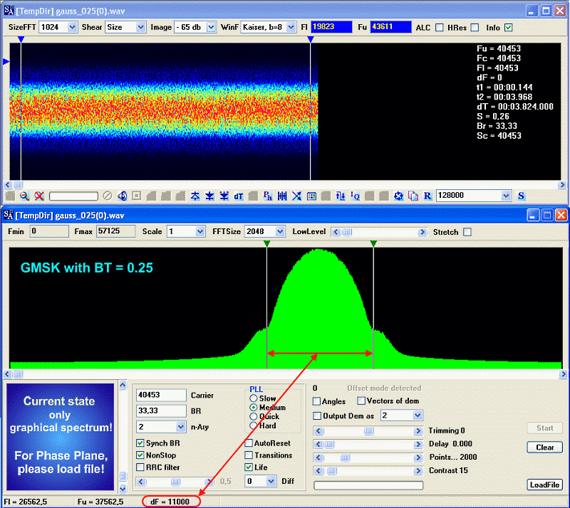
The area of concentration of the main energy is even less than at GSM, speed of falling off of the side lobes also is better than at GSM. However, noise immunity is worse than at GSM, and is even worse, than at MSK.
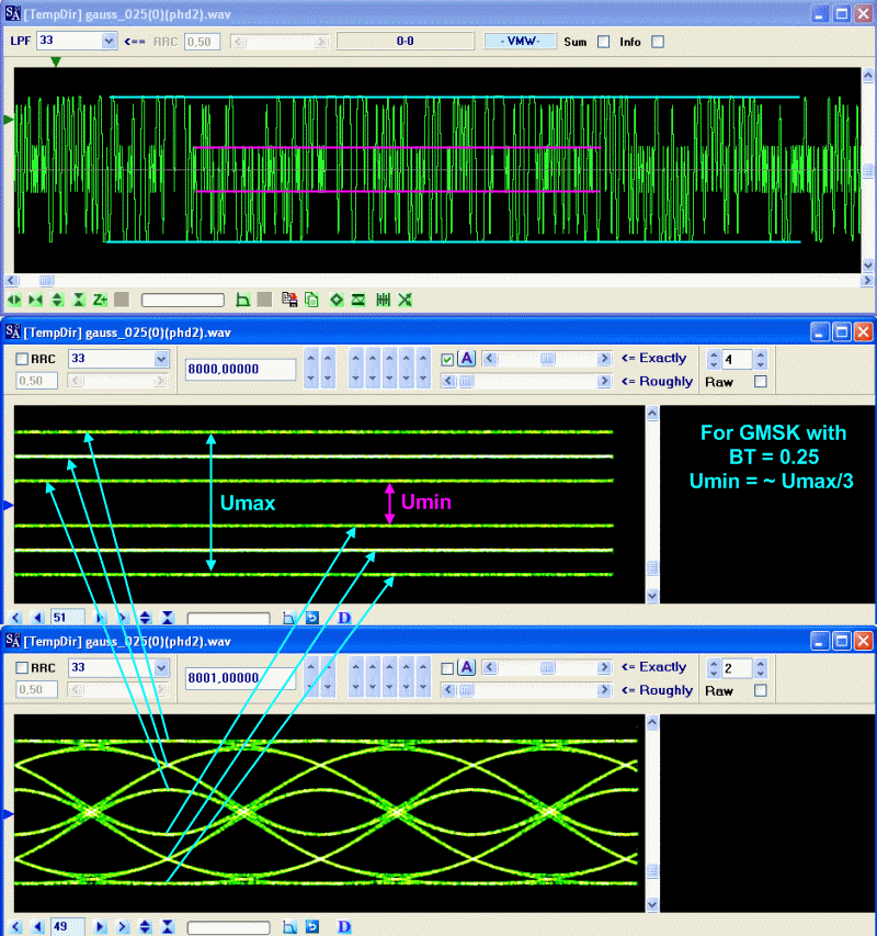
An "eye" hole on the eye-diagram is noticeable less than at GSM, it makes more rigid demands both as to clock synchronization, and to the relation signal/noise.
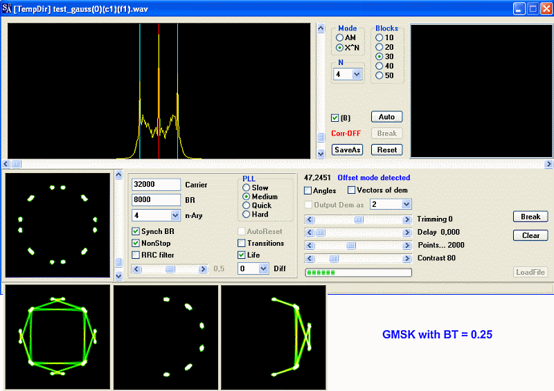
Similarity with OQPSK on the phase plane is even more.
GMSK with BT < 0.25(0.22), area of usage TETRAPOL .
The spectrum of the signal decreases even more, aspiring to value Br.
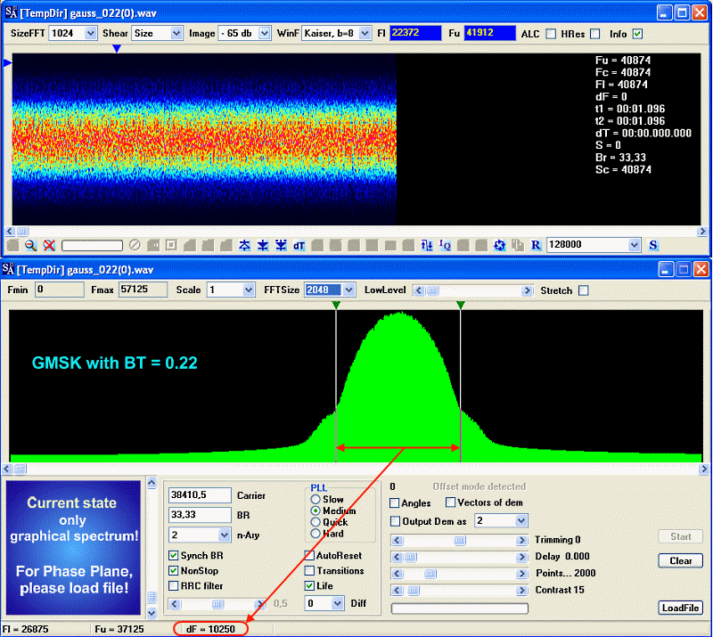
Thus noise immunity also steadily decreases, in comparison with the earlier considered signals/models.

On the phase plan even more similarity with OQPSK is appearing.

Basically it is obvious, that the further reduction BT in the shaping/forming Gaussian filter, will conduct to prompt reduction of the main lobe of the spectrum and to progressive noise immunity impairment. It seems to me that BT = 0.2 is that critical value and there is no sense to go below it. Then other decisions are necessary.
One of such decisions is OQPSK modulation.
*** OQPSK(Offset QPSK) ***
Around OQPSK much enough incomprehensible and even mystic, different sources shows differently this mode of modulation on a phase plane, on our forum hot discussions passed on this occasion. Adds a vagueness circumstance that even different determine baud rate speed, one for Br count a that value which can be selected/get from a signal, other for this value count less speed in two times.
OQPSK modulator is usually presented, as QPSK modulator with the relative change of dibits in quadrature channels on the half of time, here a time interval for QPSK is dibit. It one of reasons of disagreements in determination of baud rate for OQPSK.
One of graphic presentations of processes what be going on in OQPSK modulator, a next picture shows, it is quotation from a document “Digital Modulation in Communications Systems - An Introduction” written by Hewlett-packard company in 1997.

From this picture well evidently, that it is exactly necessary to expect on a phase plane, in addition, a tendency is obviously traced "washing" strong dibits in QPSK, in non-obvious, but sure bit(in two times higher) presentation of clock rate of manipulation in the resulting signal of OQPSK, due to a change on the half of dibit, that on one one bit of quadrature channels at forming.
To understand reasons of very large disagreements in the image of OQPSK signal on a phase plane, will consider the rough flow diagram of OQPSK modulator.

Usually as arguments for one or another reflection/shown of signal, on a phase plane give the quadrature components of signal from the points of A and B.
Synthesizing a model on such chart, risk to get a picture, different from that drawn at Hewlett-packard very much and very great.
It is a typical enough error, basic sense of which consists in that when it is talked about OQPSK as about displaced QPSK, present because of, that the signal of QPSK is formed with the use of the special formings filters. On the chart resulted higher these filters are not present, they must join in the points of C and D.
On a type and parameters of these filters depends straight, as will look OQPSK on a phase plane in the different modes of reflection/shown. The choice of filters is wide enough, and a single standard for OQPSK alike does not exist, what is one of reasons of such disagreement in relation to the type of OQPSK on a phase plane.
I will not examine the synthesized signals of OQPSK, because in a difference from GMSK, there are not clear criteria of forming, and for me does not turn out to create models adequate existent records. I shall limited to the real signals.
Example of INMARSAT Satellite .
We will consider this signal from those positions, like GMSK, because primary purpose of the article to show that GMSK and OQPSK have a lot in common, and reliably to distinguish them sometimes extremely not simply.

Basic energy is concentrated fully in the bar of Br.

Eye-diagram after discriminator, looks quite unconvincingly, although outwardly and alike on GMSK with the little indexes of BT.

OQPSK on phase plane, looks like GMSK with BT < 0.25
Actually it is an eventual point to which it was desirable to bring this article.
There are not obvious and convincing external differences between GMSK and OQPSK on occasion. Modulation of GMSK with the indexes of BT < 0.25 the nearer alike on OQPSK, the less than index of BT.
Actually GMSK and OQPSK is two sides of one medal, it becomes yet more obvious, if to remember that general chart of quadrature modulator/former of these modes practically the same, that for GMSK, that for OQPSK. "The devil hides in detail" - in the filters of formings spectrum, and if they standarizing for GMSK, for OQPSK of single approach discovering me was not succeeded.
In conclusion.
I wanted to underline the general sources of these modes/modulations, and to pay a regard to possible difficulties in a practical analysis during authentication.
It can find out differences certainly, but they are extremely unsteady, at least OQPSK “aims” to form “square constellation" on a phase plane, while GMSK “spheric/circle”.
It is not necessary to perceive this article as fully characterizing GMSK and OQPSK, it is eventual not so, small part of questions of touching is affected only practical analysis, lion's share, no less interesting aspects remained off screen.
Good Luck~
|
|
|
|
Добавлять комментарии могут только зарегистрированные, активировавшие регистрацию и не ограниченные в доступе участники сайта!
|
| Файл создан: 19 Nov 2011 21:13, посл. исправление: 19 Nov 2011 21:18 |
|

