|
|
| Разместил (Author): |
SergUA6  |
| Авторские права |
© http://www.radioscanner.ru |
|
|
Текст
|
OFDM – is one of the most difficult sorts of modulation for the analysis. The difficulties are about the fact that, the channels, at OFDM usage, as a rule, do not have clear boundaries, and thereupon it is hard to select any channel or for the detailed analysis. Sometimes, in special cases, it is possible, but not always. OFDM the technology allows to create very not trivial signals, and the classical analysis of such signals is extremely difficult and polysemantic.
The example of such difficult signal(signal1) is here Japanese Military 8 freq , compare to it this signal(signal2) Mixed mode, PSK-2 and OFDM, system unknown is even more difficult, because it is impossible to select the channel in this signal(signal2).
We will try to analyze the signal2.
But before it we will consider some common principle of analysis on classical signals, as on real ones and on synthesized ones.
The Possibility to synthesise OFDM signal with the specified parameters is very effective, at least it allows to accept some hypothesis or to reject that, it is very useful.
Let’s start.
We will consider the method of definition of the clock frequency for OFDM to begin.
This method is based on the fact, that ordinary, for OFDM synthesis use FFT/IFFT blocks with size, which exceeds size of frequency grid, are used.
That is if to use 10 frequencies, then FFT/IFFT block has the size about 16 or 32 (as example) frequencies.
There are at least several reasons for it:
it is always possible to add pair-triple of frequencies without alteration of the creator/maker’s kernel/core for perspective (and some modes are directly use the change of the number of working frequencies in the course of a session)
usage of the standard algorithms FFT, which having the blocks sizes 2^n
number not the obvious moments, when it is easier to use blocks of the larger size than it is necessary
The result of such approach, is mandatory presence of harmonious noise in the space between the generated but not used/switched off frequencies.
This harmonious noise is nothing else, but the moments of clock changings (clock frequency), which are "spread" on not orthogonal areas, in orthogonal positions, there, where the places for the grid of frequencies, this noise is equal to zero. It is perfectly visible both on the synthesised signals, and on real ones.
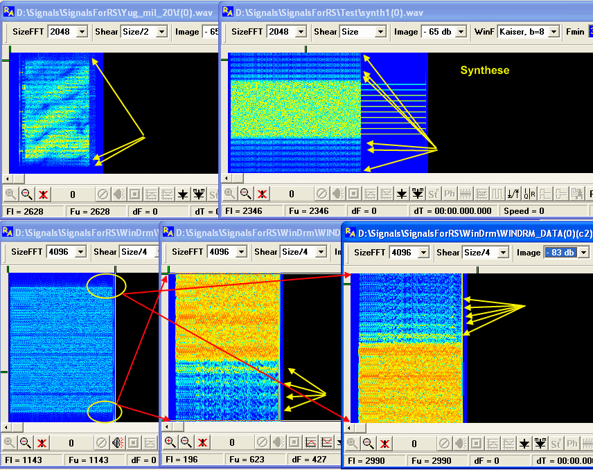
Thus, if to cut OFDM signal itself, but having left this out-of-channel noise, it is possible to receive the exact value of the clock frequency of manipulation of OFDM signal, through the classical method(capturing of envelope) or through the modified method.
There are some nuances, according to the signal’s quality it is possible to select the upper part of noise or the lower or both. It is also necessary to not confuse interferences in areas of 50-60-100-120 hertz with the clock frequency, but it is already questions of the competence of an analyst:)
Checking up the method.
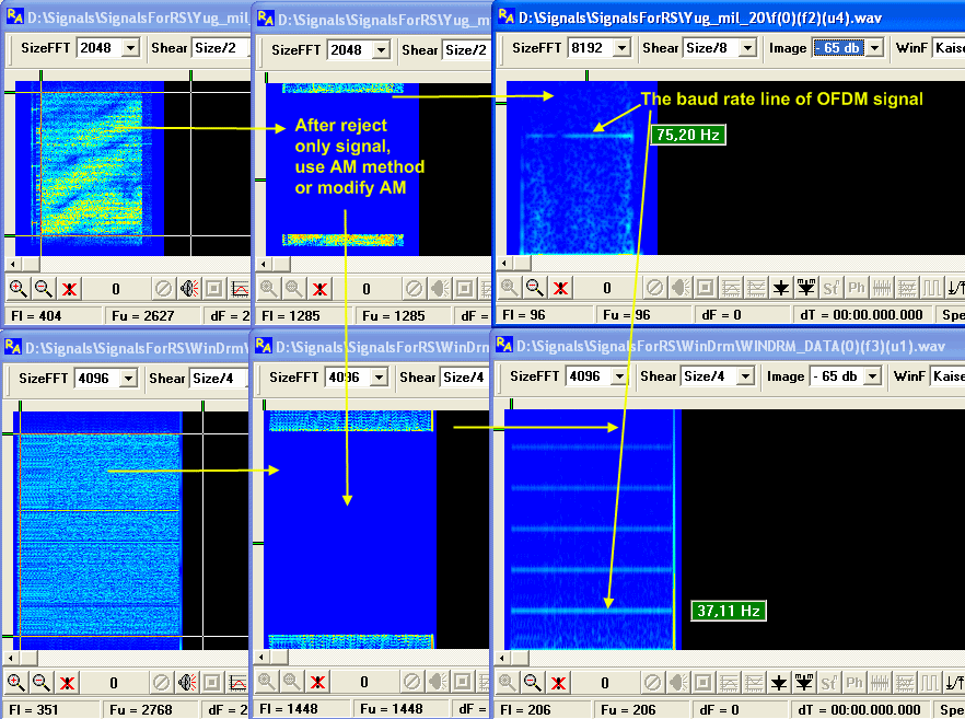
As we can see all this does work. It will work on all OFDM signals, where the out-of-channel noise is not suppressed. Actually, this out-of-channel noise has not been suppressed to zero ever. Because no one specially needs it and this supressing requires enough efforts, but as the level of these collateral/secondary components is low enough, they can be simply not exist at the weak signal, or, the most frequent reason, is the "combing" of the signal after record.
You shouldn’t do anything with the record, because it is too easy to spoil the signal.
Let’s come back to the signal. We won’t consider the part of PSK-2 and 500Hrz of manipulation, because it isn’t hard. We are interested in noise-like fragment and in the fragment with clearly visible 9 frequencies.
Formally, it is possible to identify parameters of this signal by the fragment with 9 frequencies: 9 frequencies with spacing in 80Hrz, hence, the frequencies on the noise-like fragment aren’t distinguishable and both fragments are equal by spectrum’s width. We can suppose, that cyclic prefix isn’t used and noise-like fragment – is the clear OFDM with manipulation speed also 80Hrz. But the analysis is not the guesses, analysis requires clear guarantees(as much as it possible).
If to synthesise the signal in OCG with such parameters and to put signals nearby, the differences will be visible at once, and if to measure the clock frequency, by the method offered above, we are expected by a surprise, clock is equal to 160 hertz!
The hypothesis with 9-frequencies through 80 hertz and the clock frequency 80 hertz is not well-founded. Why?
The clock frequency cannot be more than frequency spacing
It can be less (the cyclic prefix) then the frequency spacing, that means that or the method of the clock frequency receiving is not correct or the clock frequency is really 160 hertz, but then the number of frequencies is not 9 and the frequency spacing is not 80.
In reality, the method isn’t wrong, especially , the mechanism of appearance and the measuring of the clock frequency are described. That means, that there are no 9 frequencies. Then the question is: how many frequencies is there?
One of the methods to define the number of frequencies is:
800 (width of a spectrum)/160 (speed of manipulation) = 5, 5-1 = 4.
Then it is necessary, to synthesise the signal in OCG, for the control.
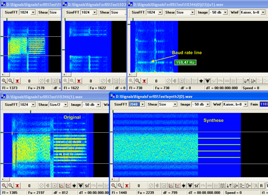
Now it is necessary to answer on two questions, what modulation is used in the channel, and why there are 9 frequencies are clearly visible in the second fragment?
Despite that these questions are facultative, it is desirable to find out the answers on them. Purely we check the next hypothesis: it is OFDM with 4 channels, with spacing in 160 hertz and speed of manipulation in 160 hertz. As in the first fragment it is impossible to select the channel qualitatively without the special demodulator, it is necessary to pay special attention on the second fragment. The selected fragment represents doubtless interest.
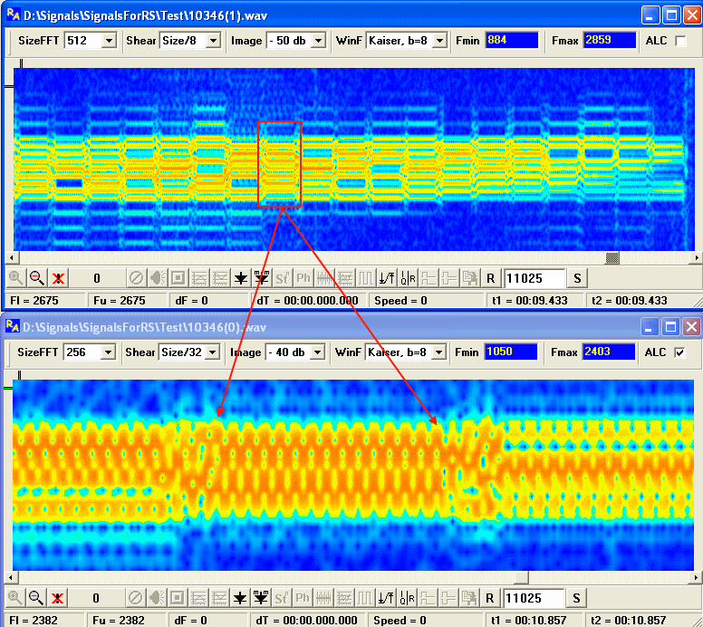
I do not have any other explanation to such "chess" arrangement of these "knots", as using of one trick at the manipulation with frequencies.
Most likely the frequencies are manipulated through the step/clock approximately by scheme represented below, where:
х – the frequency is turned on,
0 – the frequency is switched off on a current step
Freq4 0x0x0x...
Feqr3 x0x0x0...
Freq2 0x0x0x...
Freq1 x0x0x0...
That is only supposition, but can check it:
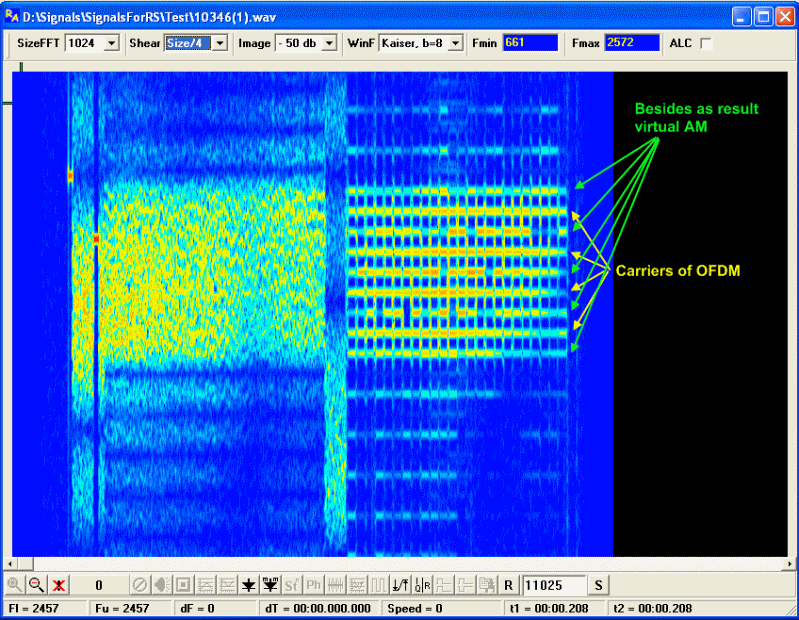
Actually we have four frequencies with 100 % amplitude modulation with frequency of 80 hertz, that gives four carriers with step in 160 hertz (the grid of frequencies), and with laterals by both sides from each of carriers on distance of 80Hrz. That should give 9 (!) lines on the spectrum, because the laterals of neighbour carriers are coincident.
Only little thing is remained to check up it practically. Unfortunately OCG does not give the possibility to synthesise similar signals, but as you understand for me it is not strongly big problem. We synthesise it and compare – the result is 100 % hit and coincidence.
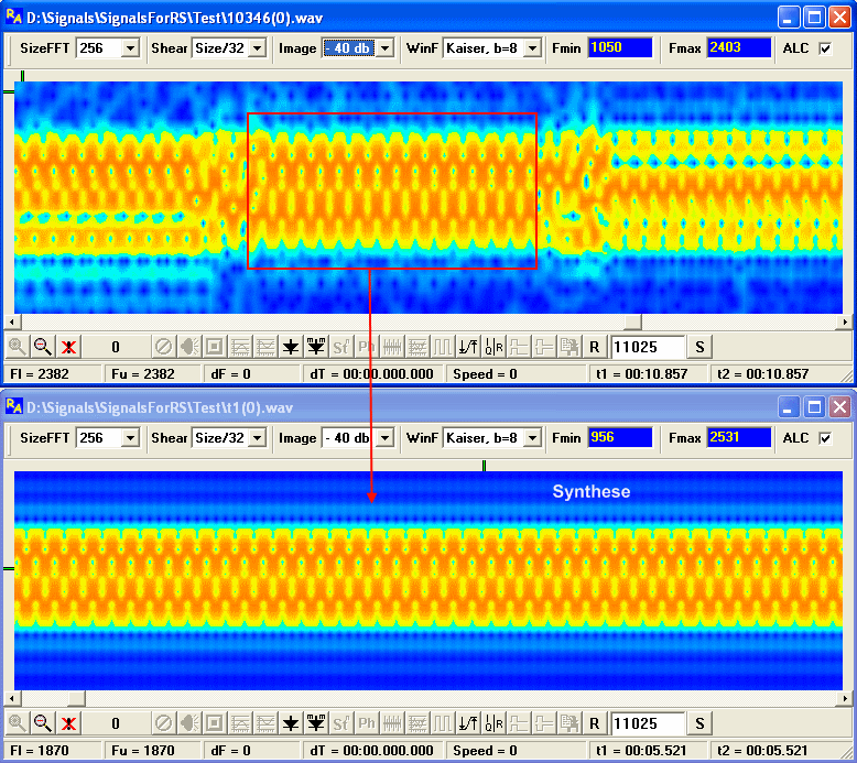
Thus, we get very interesting signal. Virtually manipulation in the channels is 80 hertz, but the general manipulation and real is equal to 160 hertz.
Why the virtual manipulation is 80 hertz? Because, it is necessary to take samplings with duration 1/160 sec and supply it on FFT demodulator, to demodulate the signal correctly. If to take the samplings with duration 1/80 sec, then it is impossible to demodulate the signal correctly.
Why the laterals on the second fragment are absent or have small amplitude sometimes?
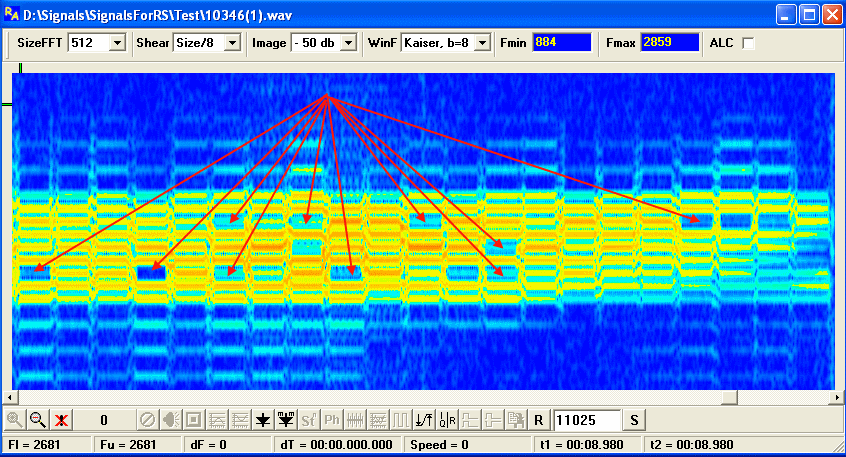
The common laterals of two adjacent working frequencies can destroy each other, in case, if they have the difference of phases in 180 degrees. It means, that besides all, the phase manipulation of the carriers is used. Lets try to define the order of this manipulation.
Unambiguously, PSK-2 is not used PSK-2. It is enough to play with the synthesis in OCG to check it for sure. So we have or PSK-4 or above, or QAM. It is not possible to answer this question with 100 % a guarantee, but we can try to define it.
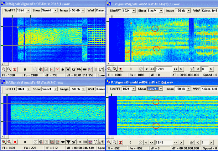
If all reasonings and conclusions are true, and if to synthesise a similar by parameters signal, then any identical distortions as for original and for model, should give very close results. We can to define an order of modulation in the original signal, by changing of order of the phase modulation in synthesized signal.
It is necessary to find such distortions of the original signal, which will give bright enough and characteristic picture. Not the fact that it is possible, but in this case, exponentation of the noise-like signal in the eighth degree gives interesting enough result. Exponentation of the synthesised signal, with modulation in channels PSK-4 gives very similar picture.
As soon as it has been defined that there are 4 frequencies, and both the speed of manipulation and the frequency spacing are equal to 160 hertz, formally analysis of the signal is completed. This information is quite enough of for the competent work of the demodulator, as only the demodulator will give the exact and guaranteed answer about arity of manipulation in the channel, and possible about the presence and of amplitude manipulation. But after all it was interesting...:)
There is something else. The question what is all that for? After all not for this purpose that analysts would puzzle over a signal (though also this variant is not eliminated), there should be a rational grain in such manipulation as a variant I can offer that the similar approach allows to select rather reliably and simply clock rate under trying conditions, is much easier than with a cyclic prefix, does not break conditions of orthogonality and probably has still what pluses, but in general and it достачно for a substantiation that all outputs are more likely true, than are roughly erratic.
As a variant I can offer that such approach allows to define rather reliably and simply the clock frequency in difficult conditions. It is much easier than with cyclic prefix, it does not break conditions of orthogonality, and probably has more pluses, but in general and it is enough for the substantiation. And all conclusions are more likely true, than are roughly e erroneous.
Good Luck.
|
|
|
|
Добавлять комментарии могут только зарегистрированные, активировавшие регистрацию и не ограниченные в доступе участники сайта!
|
| Файл создан: 27 Jun 2009 15:32, посл. исправление: 27 Jun 2009 15:47 |
|

